Best in Class

Note that this website uses tracking cookies. By viewing these pages you are automaticlly consenting.

Survivor Antennas
News Page

Updated 5/22/2022

I'm finally getting my shop set back up. Thank you for all who have shown and interest in my products.  This is going to be an exciting year with new advances and designs to show you.  Stay tuned... Ke4LH


Home

News

Antennas

Photo Gallery

Testimonials

Contact us


A Mobile CB antenna is in the works, check back soon.  Also a new base station CB antenna is in the works .  A SWL short wave listening antenna capable of 1.8 to 50 mhz recieve with low noise characteristics is still on the drawing table, just too many projects and not enough time. 

 note: You may contact me with questions at any time. Use the Contact us link to the left.

For those of you who have the calculator program I offered, you may freely use it until further notice.  It is safe to use, has no back door or advertising or virus.


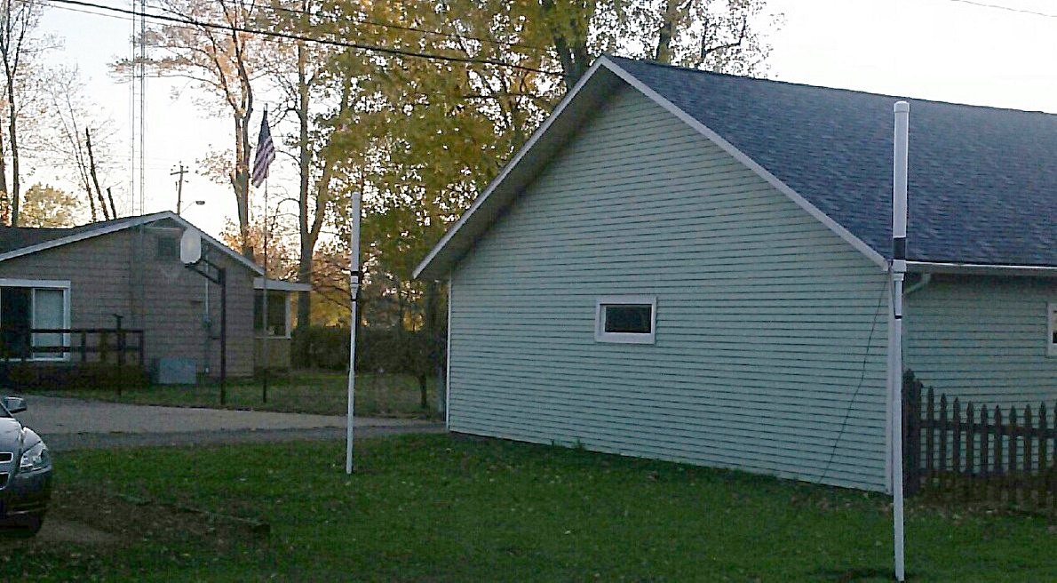
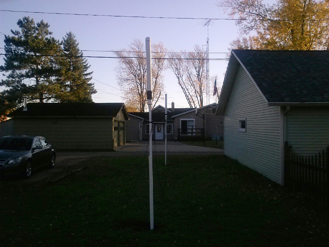
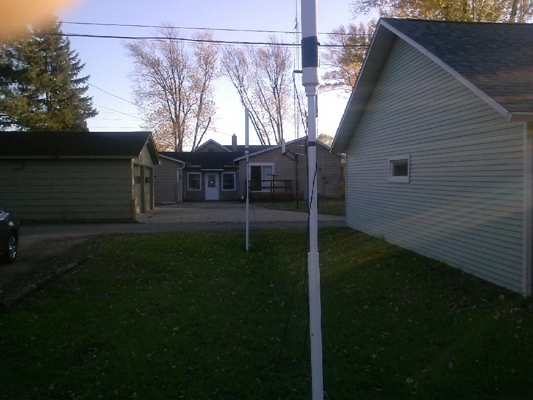
Testing  results on Paired Antennas for 80 meters

Months of testing over the fall and winter of last year has rendered some surprising performance results!
A pair of 1SM80-4's, daisy chained together was tested in an attempt to lower the noise over a single antenna by adding more capacitance to the array. (It's long been known that large capacitance antennas are low noise)
The results far exceeded our expectations.  The location: Northern Wisconsin.  Constant year around noise level is 8+ S units.  Noise reduction was steady and reliable reduction of noise by 6 S units.  Then something else was discovered.  After a contact to Hawaii running only 100 watts, we discovered the array was directional.  With an estimated front to back ratio of better than 20 db the array was tested in the N/S configuration pointing South.  Canada stations disappeared and contacts to the southern part of the states was very good.  Note that this array was mounted 6 ft off the ground with the top of each antenna at 10 ft.  Masts were used simply pushed into the ground.

Another discovery was the paired array works very well on some of the other (harmonically related) bands.  Particularly 17 meters (lots of contacts and dx) and also on 20 meters with a tuner.  It was also tuned to 40 thru 15 meters and loaded well with just the internal tuner in an Icom-756.   Click pictures for a larger view.

August 30, 2011  See below for a unrevealed feature of the design......

I'm working on a 2 meter design that has been field tested for months now. It is 1.5 inches long and has 2dbd of gain referenced to a 1/4 ʎ ground plane.  Also a second generation is in the works with even more gain.

I have built a version that no longer needs or uses a delay line. Performance is about the same as the regular version.  I call it V2 for version 2 and it is patentable.  I do not offer it for sale yet as I have not decided on patenting this version.


Recently I had the honor and privilege to test a new design with a friend who works in the cell phone industry.  He has a very expensive service monitor made by Anritsu and Motorola.  I built a full size 1/4 wave ground plane for 2 meters to compare to the new design and testing was performed outside the direct field of one wavelength.  Gain indicated as compared to the ground plane was measured at 2 dbd which is amazing considering the antenna is only 1.5 inches tall!
I am hoping to be able to purchase an antenna analyzer that will operate on the vhf/uhf frequencies soon so I can finalize the design and bring it to manufacture for you all.  I have been running this antenna inside my house at a distance of 20 miles from our repeater located in Texarkana, AR/TX with 20 watts as band conditions are poor at the home location.  Frequently I could not hit the repeater with 50 watts from a 5/8 wave on my car from this location.  Of course on VHF, positioning is everything when you're in a poor location and I'm sure the 5/8 wave would also work in the same location in the house.  But the proof is in the equipment and I am thankful for my friends help and use of the equipment that day.  If I get permission, I will mention his call and name and if he is willing, and contact information to verify what I say.  It was his equipment we used, and the Anritsu  monitor is very expensive.

There was also some testing done on the 1SM40 meter antenna.  Some properties were discovered that will be even more surprising than what I mentioned above.  Here is just one of those:  The 2 meter design tested above is based upon the same calculations and design criteria as the HF antennas, in other words, it was scaled up from the 40 meter design exactly. What does this mean?    It is now thought that ALL the HF designs have 2 dbd of gain. This explains their excellent performance, particularly on  DX running barefoot. NOTE that 2 dbd of gain is only a gain for 1.57 or with 100 watts input, a radiated power of 157 watts.  Still, that is much better than a 6 to 20 db loss in conventional designs.

There are other, even more interesting things that were discovered about the 1SM40 we tested that day.  Some are unbelievable, and others are quite surprising like the gain estimate.  August 30th, 2011:
Here is a very interesting update,.... The day we tested the 1SM40 a strange thing was discovered.  The 1SM40 also exhibits 3dbd of gain on 2 meters!!! This measurement was taken without the delay line using a direct connection with a short run of coax...  I tweaked it and got the swr down to 1.2-1 and we compared it to our ground plane and once again, at distance of several miles, the antenna proved to outperform our reference design. Stay tuned for more....


Keep the Net Free

 r